
Digital and SMS/Email-enabled Alarm Output
Digital Alarm Output provides manual and auto-closed-loop control for WinDaq system, as well as Audio, SMS or Email alert (experimental) when a alarm is triggered
-
Features
- Actions
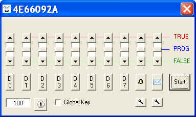
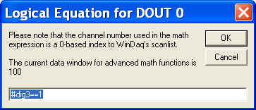
Use button D0...D7 to enter the logical equation for the corresponding digital output.
Lower DIO channels on DI-2108/4208/4208/2008 are reserved as input by WinDaq, to use them, check Use All DO option.
Please configure the corresponding DIOs on DI-71x to outputs if you wish to use the digital outputs with DI-71x
SMS/Email and Audio Alarm
Button
to enter the logical equation for the SMS/Email alert.
Button
to enter the logical equation for the audio alarm
Button
under
Button
The first parameter is the keep alive interval (in minutes) for SMS/Email periodical reporting. Enter 0 to disable this feature
The second parameter is the hold-off time (in seconds) for the next alarm email once an alarm is triggered. Enter 0 to disable the hold-off feature.
Use All DIO for Outputs. On DI-2108/4108/4208/2008, DI0..D3 are usually reserved for inputs as Event, Record, Rate and Counter channel. By choosing this option, all can be changed to outputs. If some of the input functions are needed in WinDaq, set the Dout to TRUE manually and you can send the digital signal to the port. For example, manually set D3 to TRUE, you can use D3 as counter channel in WinDaq.
Warning: If you wish to use Digital Inputs, Event, Rate or Counter inputs after you are done with the control, please either recycle the power on the instrument or manually set all DIO to TRUE before you exit this add on to reset the direction for all DIOs. WinDaq will not initialize the direction of the port.
Data Window Size determines the number of data points when evaluating MIN, MAX, AVE, RMS and ACRMS
Slides has three states. It controls the state of a corresponding output.
TRUE: assign TRUE unconditionally
FALSE: assign FALSE state unconditionally
PROG: Set the output to TRUE if the logical expression for the corresponding channel renders TRUE
For digital outputs, please refer to product manual to find out the meaning of TRUE and FALSE output.
For Audio alert, TRUE plays the sound file. FALSE stops the sound file
For SMS/Email alert, TRUE generate periodical report if report interval is greater than 0. FALSE stops any SMS/Email alert.
Keyboard operations when addon is in focus
Key 1,2,3,4,5,6,7,8,9 to set D0,1,2,3,4,5,6,7 and Alarm to PROG
Key Q,W,E,R,T,Y,U,I,O to set D0,1,2,3,4,5,6,7 and Alarm to TRUE
Key A,S,D,F,G,H,J,K,L to set D0,1,2,3,4,5,6,7 and Alarm to FALSE
Logical Expression
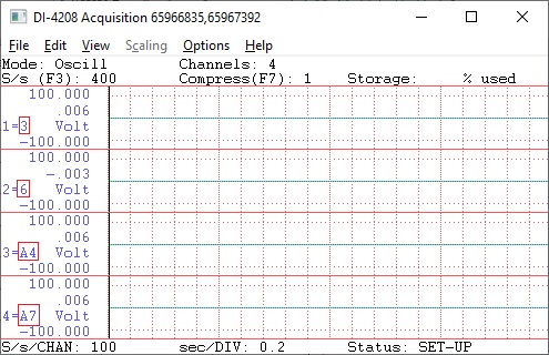
To use the reading from a channel, use CH notation, the channel number after this should match what you see in WinDaq. For example, CH3, CH6, CHA4 and CHA7 are available in the following WinDaq configuration
True math expression
Operators include: +, -, *, /, ^, %, &, |, !, >, >=, <, <=, !=, ==
Functions include: abs, floor, round, log, sqrt, ceil, log10, acos, asin, atan, sin, sinh, cos, tan, cosh, tanh
Data-window based readings
To use the data-window derived results, use MIN, MAX, AVE, RMS and ACRMS to represent Min/Max/Ave/RMS/ACRMS in the expression, i.e, CH1ACRMS returns the AC_RMS reading of channel 1 in the sampling window, CH2MIN returns the minimum reading of Channel 2 inside the sampling window.
The length of data window should be selected properly, especially in RMS or ACRMS mode, or wrong result may be generated.
Extra Controls. Besides the standard logical expression like CH1>3, extra controls are available
The syntax has three parts, separated by comma ","
Optional first part address how long the delay should be before the logical expression is evaluated, and its syntax is DELAY n, where n is number of seconds to delay. For example, DELAY 100
Second part is the standard logical expression. For example, CH1*CH2>10
Optional third part is if further comparison should be conducted, and its syntax is HOLD if the answer is no. In this mode, the trigger waits for the change from the initial state of the logical expression, for example, we use CH3>1, HOLD as the expression
If CH3 is lower than 1 when the the addon is started, it waits until CH3 is higher than 1 before entering the HOLD state
If CH3 is higher than 1 when the the addon is started, it waits until CH3 is lower than 1 before entering the HOLD state
Here are some examples
CH3>1: This is just the standard logical expression, without the optional part 1 nor part 3.
DELAY 20, CH3>1: Do nothing for 20 seconds, then perform the comparison and output to Dx based on the result. Without the optional part 3.
CH3>1, HOLD: Once the reading on CH3 changes, the output will remain unchanged. Without the optional part 1
DELAY 20, CH3>1, HOLD, all three parts are present
Button [i] is for debug purpose output, it displays the logical expression for each DOUT, along with internal format for the expression, for example
Delay =10, Trigger=#0>3, HOLD=False shows the delay length, index-based trigger channel, and hold setting
SMS and Email Alert (Experimental)
Sends out email automatically when alarm is triggered
Periodical (Keep Alive) email
Keep Alive email will be sent out periodically to let the user know that WinDaq is still running
Keep Alive email's interval is stored in c:\windows\ultimaalarm.ini, under the key of EmailAlarmInterval. The default interval is 20 seconds, to remove Keep Alive, please change this number to 0.
Allow modification of alarm re-arm interval (in minutes)
Three options
TRUE: Only periodical SMS/Email output if it is enabled
PROG: Alarm-triggered SMS/Email output, and periodical SMS/Email output if it is enabled
FALSE: No SMS/Email output
Push the button
The first parameter is the keep alive interval (in minutes) for SMS/Email periodical reporting. Enter 0 to disable this feature
The second parameter is the hold-off time (in seconds) for the next alarm email once an alarm is triggered. Enter 0 to disable the hold-off feature.
- Notes
- Not every data point is tested against the trigger condition, a compromise is to use data-window derived results, such as MIN, MAX, AVE, RMS and ACRMS . The add-on is paced by Windows' timer, up to 50Hz.
- Due to the limitations of the hardware, when using with 720/730 USBs, please make sure Windaq's maximum sample rate doesn't exceed 100K, and the sample rate is less than 50K
- When ChannelStretch is used, D0-6 appears in the first instrument only (If you have the need to control DIOs on the other instruments in ChannelStretch, please let us know)
To Use WinDaq Add-on Digital and Alarm Output
Start WinDaq
Invoke Windaq->View->Add-ons->Digital and Alarm Output
Configuration file
If you can't find it there, you may need to look in C:\Users\...\AppData\Local\VirtualStore\Windows
Last update: 07/23/24
© www.UltimaSerial.com